Most build guides present the final design as though it arrived whole. This one did not. Several decisions got reversed, one mistake cracked the pier, and two questions were never satisfactorily answered.
The reversals are more useful than the conclusions, so here they are.
The one that actually damaged something
Day one after the pour, the top rotor came off to clean concrete splash from both discs. That part went fine. Putting a nut back on, a thread picked up some concrete and the nut seized — and it got torqued anyway.
The rod turned in concrete that was about 24 hours old. Set, but nowhere near strength.
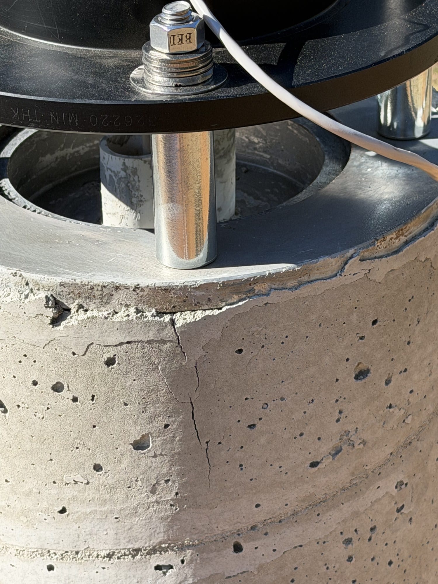
What followed: a short vertical crack at the top of the pier beside that rod, and a larger one roughly two feet below, about where the buried nut sits. Both consistent with a rod rotating and splitting concrete that could not yet resist it.
Why it was recoverable
The buried nut and fender washer on each rod provide mechanical anchorage — they resist pull-out by bearing against concrete, not by bond along the shank. Twisting the rod breaks the bond. It does not remove the nut.
That detail is the only reason this was a setback rather than a demolition job. It is also the argument for specifying it in the first place: it costs a nut and a washer, and it is the difference between one damaged rod and a failed pier.
It is also one rod of four, and the rods do not carry the mount's weight — the concrete does. The rods clamp the adapter down.
What to do instead
Never torque against a seized nut. Cut it off. A ten-dollar nut is not worth a pier.
Never put a wrench on a rod that has twisted in green concrete. More torque only enlarges the damage.
Do not fill the cracks immediately. Filler adds no strength, and while the cracks are open they are your instrumentation — the only way to tell whether anything is still moving. Mark and date both ends, measure the width, and re-check at 14, 21 and 28 days. Static cracks are cosmetic; growing ones are not.
Reading the two cracks
They are not the same thing, and it is worth being able to tell them apart.
The lower one is ordinary shrinkage. It wanders, changes direction, crosses the form's spiral seam without following it, and branches. Structural cracks run straight and follow stress. Shrinkage cracks meander. Every 12″ column does this.

The upper one is the rod. Vertical, running down from the top edge, tapering as it goes. But it is hairline, and there is no cone-shaped pattern radiating from the rod — which is what an anchor actually pulling out would produce.
The design reversals
Ring blocking on the wrong lines
The first framing plan put the dome's ring blocking on convenient grid positions. It looked fine in a solid view. Rendering a framing plan made it obvious the blocking was sitting in the field carrying nothing, while the 88″ circle where the dome's load actually lands had wood under it only by accident.
Rendering the view that shows the thing you are checking is worth the extra step.
The bay that fit by 0.6″
An early 10 × 10 layout put the bay at 45° with 0.6″ of clearance and called it a fit. Sweeping every angle showed 45° was the only angle that worked, and by less than a pencil line.
"It fits" and "it fits with margin" are different claims. The fix was not a better measurement — it was noticing that the dome did not have to be centered at all.
A pier that was flexing more than the pier
The adapter's first design used stacked washers as spacers across a 3¾″ gap. Modeling it showed the adapter accounting for 68% of total system compliance — flexing more than twice as much as the concrete pier under it.
Nothing about that was visible by looking at it. Four ½″ rods look substantial. Bending stiffness goes as diameter⁴ and compliance as gap³, and those two exponents were doing all the work.
Seven washers is not a spacer
After the rod incident, the damaged thread section got bridged with seven stacked washers. That is a springy load path — washers dish under clamp load and the joint loosens over time. A single solid steel sleeve cut square to the gap does the job properly.
The trammel that could not exist
Three methods for centering the wall ring were proposed before one worked.
The first was a trammel pinned at the pier center — impossible, because the center point is inside the pier.
The second measured from the pier's surface — geometrically sound, but it produced a 1″ spread because a concrete surface formed in a cardboard tube is not a datum.
The third measured the ring against itself using chords, and worked immediately.
When a measurement keeps disagreeing with itself, suspect the reference before the thing being measured.
Hanging the cage from the template bar
An early sequence had the rebar cage hanging on wires from the same crossbar holding the adapter. It does not work: the bottom rotor is 11″ inside a 12″ form, leaving no clean path for hanger wires, and anything threaded through gets pinched when the rotor beds.
Two plywood templates
Another version called for two plywood templates 12″ apart to keep the rods plumb. The rods only project about 5″ above the pour — there is nowhere to put a second template.
The smaller corrections
| Claimed | Actually |
|---|---|
| Diagonal is 169¾″ | 169-11/16″ |
| Cut footing cross ties to 22″ | 11″ — a 13″ hole cannot take a 22″ bar flat |
| Paint the whole adapter against rust | Leave embedded steel bare — concrete passivates it, and paint kills the bond |
| Use cutting fluid on cast iron | Drill it dry — graphite is self-lubricating; oil makes abrasive paste |
| Anti-seize every thread | Never on anything the concrete touches |
| Trim-head screws for decking | Bugle head — trim heads pull through |
What was never resolved
Two questions are still open, and they should not be quietly closed by anyone adapting this build.
The NexDome door swing. Whether the door opens inward, outward, or slides was never confirmed from the manufacturer. The 24″ apron is comfortable for a sliding or inward door. An outward swing needs clearance equal to the door's width, which 24″ is not. This is a question for NexDome, not for a guide.
Wind anchoring on a floating deck. A 250 lb dome is a sail, and a floating deck resists uplift only by its own weight. Four ground anchors is a reasonable floor — it is not a manufacturer specification, and it is not engineering.
The pattern worth taking away
Almost every error above came from the same place: a number that looked authoritative without being checked against the thing it described.
Blocking placed on a plan that was never rendered. A clearance quoted from a diagram rather than computed. A datum assumed to be flat because it was concrete. A spacer assumed rigid because it was steel.
The cheap fix in every case was to render the view, run the arithmetic, or measure the reference — before committing. The expensive cases were the ones where that did not happen until after.