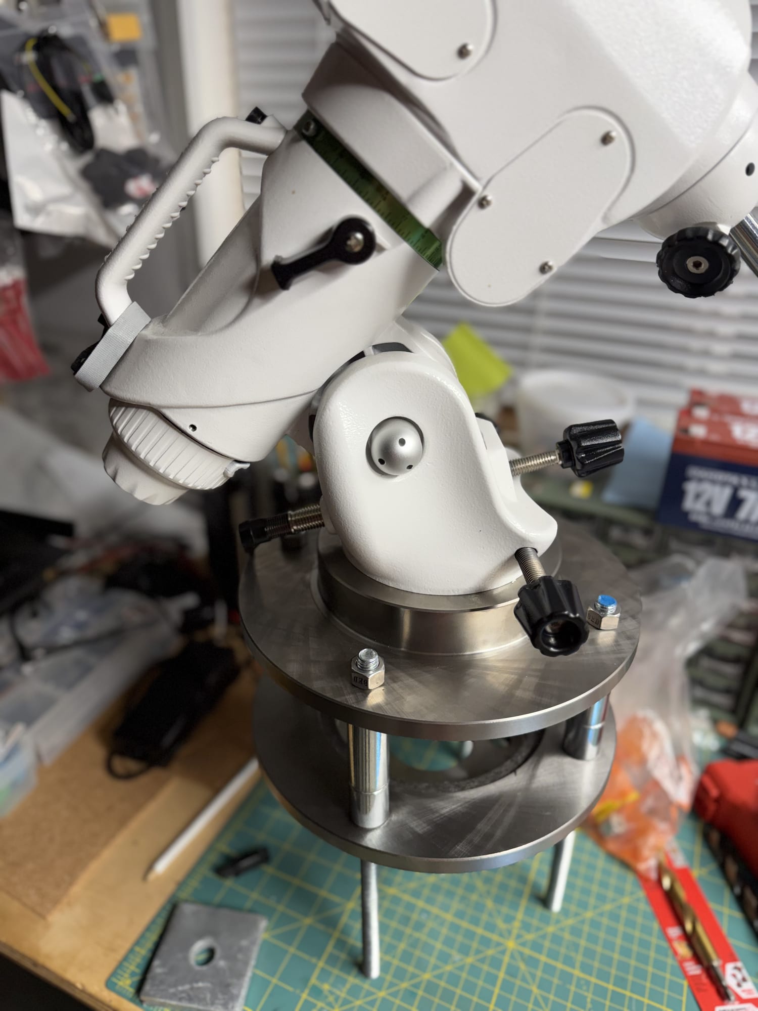
The adapter connects a 12″ concrete pier to an EQ6-R Pro. It is made from two solid 2012 Chevy Malibu brake rotors, whose center bore happens to fit the mount exactly, joined by four ½″ threaded rods on a 6¼″ square.
Brake rotors are a good choice for this: heavy, cast iron, machined flat, cheap, and the hub gives a ready-made cable path.
The stiffness problem
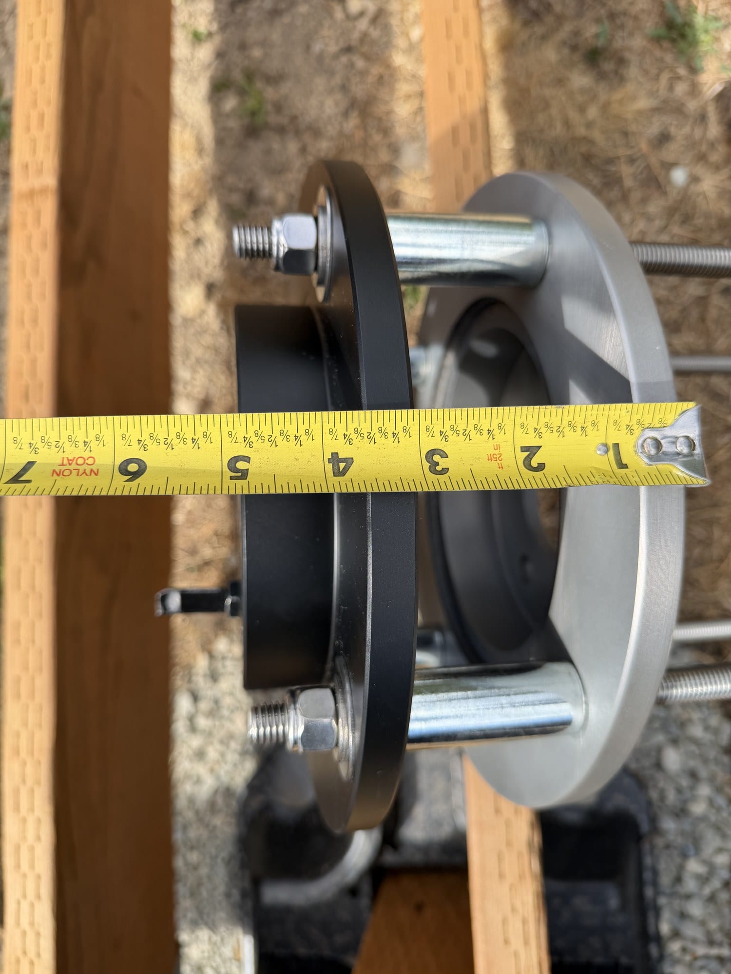
The original design separated the two rotors by 3¾″ using stacked washers as spacers. That felt like a detail. It was not.
Modeling four ½″ rods as a short frame, with the scope's mass about 15″ above the mount face, the extension accounted for about 68% of the total compliance in the system. The adapter was flexing more than twice as much as the entire concrete pier beneath it.
The reason is brutal arithmetic: a ½″-13 rod's root diameter is 0.406″, and bending stiffness goes as diameter⁴. One rod has an I of 0.0013 in⁴. Four of them are still nothing next to concrete. And compliance goes as gap³, so 3¾″ of unsupported rod is where all of it happens.
| Configuration | Adapter's share of total flex |
|---|---|
| As first designed — 3¾″ gap, washer spacers | 68% |
| Gap reduced to 2″ | 31% |
| Gap reduced to 1¼″ | 17% |
| 3¾″ gap + 1.5″ OD tube spacers | 31% |
| 1¼″ gap + tube spacers | 4% |
Why the gap could not just be closed
The EQ6-R clamps to a center bolt fastened from below. That means permanent hand-and-wrench access underneath the top rotor — the gap is not optional.
Two solutions were considered:
Non-shrink grout. Fill the gap after alignment, so load transfers concrete → grout → disc instead of through the rods. This is standard practice for steel column base plates and gives the stiffest result. But it seals the underside access permanently, which this mount cannot accept.
Steel tube spacers. Four pieces of 2″ OD × 0.25″ wall tube, one over each rod, bearing directly on the rotor faces. Keeps the center open, stays reversible, and lands at about 4% of system flex in the table above (the 1¼″-gap row) versus grout's under 1%.
The difference between 4% and 1% is not measurable against seeing and wind. The spacers won.
What the spacers demand
Ends cut square and faced flat. A crooked end bears on one edge and you lose most of the benefit. Worth facing on a lathe, or at minimum chop-sawing and dressing on a belt sander against a square.
Nothing between the spacer and either rotor face. No washer, no nut. That steel-to-steel contact is the entire mechanism.
Level with shim stock, not nuts. With grout you level on leveling nuts. With spacers the tube must bear directly, so leveling happens with stainless shims under each tube — standard millwright practice for machine bases.
Keeping the bottom rotor
One design iteration removed the bottom rotor entirely, putting the rods straight into concrete. It came back, for a reason that is not obvious:
Four 2″ tubes have only about 5.5 in² of total bearing area. Torque those nuts to even 20 ft-lb and you are putting ~2,200 psi on screeded concrete — close enough to its strength that it can creep over years. A cast-iron disc spreads that load across its whole face.
Rod choice
Strength was never the constraint. The static load is under 100 lb; even unrated hardware-store rod is enormously overbuilt.
What mattered was that these four rods can never be replaced without destroying the pier, and that the 6¼″ square leaves only 1.33″ of cover — just under the 1.5″ convention.
304 stainless was the answer. Not 316 (unavailable locally, and its chloride advantage is irrelevant for concrete embedment plus a sheltered dome). Not B7 (strength you do not need, bare alloy steel that rusts). Not electroplated zinc (a few ten-thousandths of coating). Hot-dip galvanized would also have been correct — F1554 galvanized anchor rod is exactly this application.
Match the hardware to the rod. Stainless rod → stainless nuts and washers, and nickel-based anti-seize on every exposed thread, because stainless galls against itself. Galvanized rod → galvanized nuts, oversize-tapped for the coating, and no anti-seize.
Anti-seize has one hard rule
None of it on anything the concrete touches. The embedded length relies on bond, and a greasy film degrades it. The buried anchor nut and washer go on dry. Anti-seize is only for threads you will turn again.
Hardware, per rod
Bottom to top: buried nut + fender washer + nut · nut + flat washer under the bottom rotor · bottom rotor · tube spacer, bearing directly · shims · top rotor · fender washer + nut · jam nut (optional).
Four nuts plus an optional jam nut, two fender washers, one flat washer per rod — 16 nuts (20 with jam nuts), 8 fender and 4 flat across four rods, plus spares.
The fender washers earn their place in exactly two spots: at the top, where the holes are ⅝″ and a standard washer would sit half in the hole; and at the buried anchor, where the large surface is the pull-out resistance.
Hole sizes: asymmetric on purpose
Top rotor opened to ⅝″. Bottom rotor stays ½″.
Four rods cast in concrete will never land accurately enough to drop a rotor over four ½″ holes — thread crests alone can bind it. The top rotor needs 1/16″ of slop per side.
The bottom rotor does not, because it is the drilling template. Tight holes there are precisely what makes the rod pattern accurate.
Opening cast iron from ½″ to ⅝″ with a twist bit is where bits grab — the center chisel edge has nothing to cut, so the outer lips catch the existing hole and the bit self-feeds. Clamp the work, run 300–400 rpm, and step up ½ → 9/16 → ⅝ if you can. A carbide burr in a die grinder avoids the problem entirely and cuts the slots in the same operation.
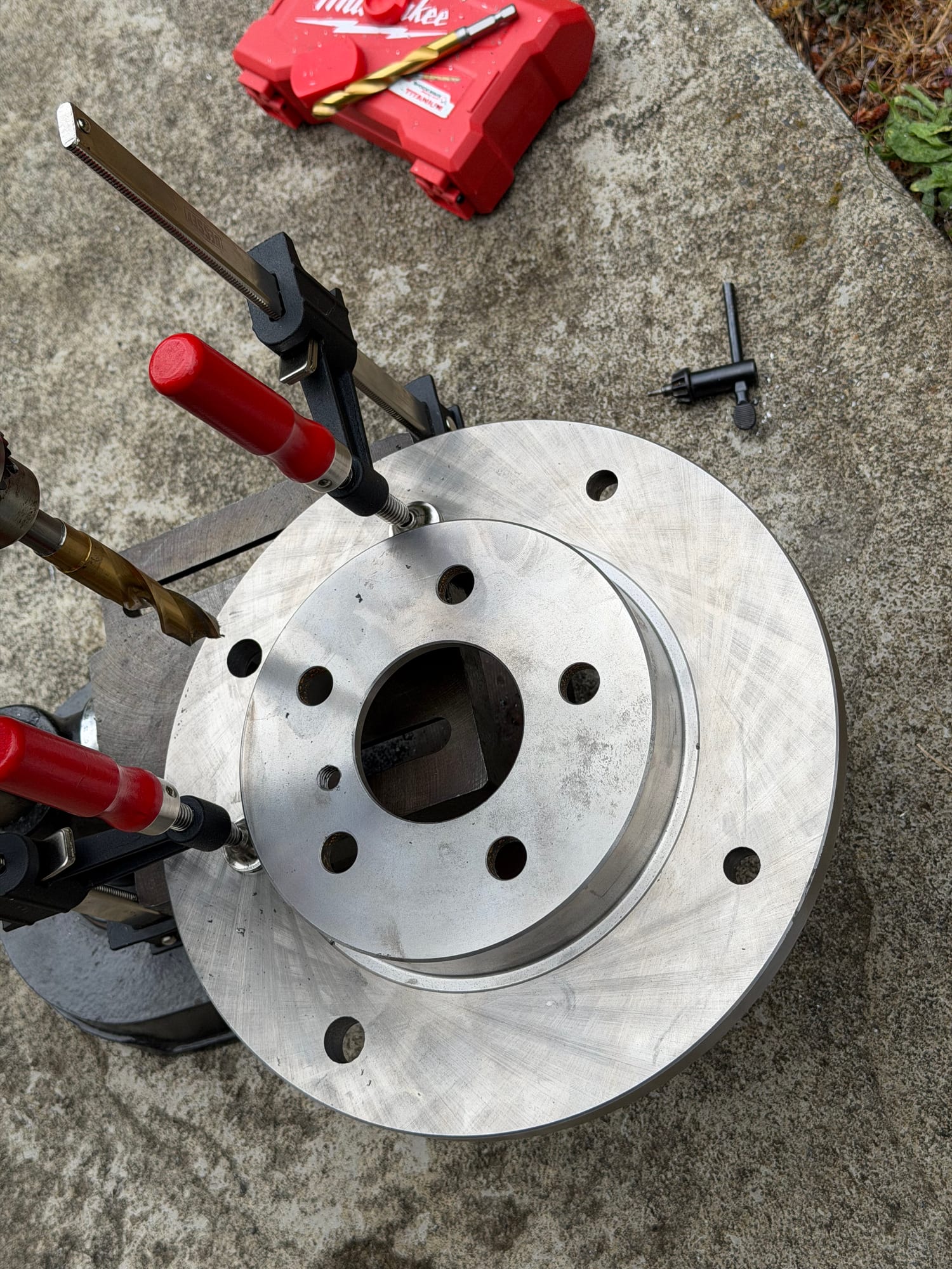
Drill cast iron dry. The graphite is self-lubricating, and oil turns the dust into an abrasive paste. Wear a respirator — it makes fine dark dust, not chips.
The index rod
A rod fixed to the top rotor gives the mount's azimuth adjusters something to bear against. It has to point true north.
Because the rod square is a 4-position pattern, the top rotor can only mount at 90° increments — so its direction is set by how the bottom rotor is oriented in the wet concrete. Hole clearance alone buys about ±0.8°.
Two things make that survivable: scribe a witness mark on the bottom rotor aligned to the index rod during dry assembly, and consider slotting the top rotor's four holes into short arcs — about ½″ of travel gives ±3° of rotation, turning a one-shot alignment into an adjustable one.