The pier carries the telescope and nothing else. It is the one part of the build where stiffness matters more than strength, because what ruins an image is not collapse — it is movement measured in arcseconds.
Depth: 36″, and not because of frost
The county's residential design criteria put frost depth at 12″ for all low-land areas.
Source County residential design criteria, rev. 2024-03-26 — https://www.piercecountywa.gov/DocumentCenter/View/4405/Bulletin-Residential-Design-Criteria
The pier went to 36″. That is three times the frost minimum, and the reason is not frost at all. It is that 12″ is barely below the seasonally active soil layer, and a pier that moves ruins guiding. Depth buys stability.
The hole is about 13″ across for a 12″ form, giving an earth-formed footing slightly wider than the column — which is the correct relationship. If you can, belling the bottom 6″ out to 16–18″ resists both frost lift and tilting.
Diameter: 12″, arrived at sideways
The pier was designed at 10″ until the adapter's bolt circle turned out to be a fraction over 10″ across, which would have put the nuts at the form's edge with zero concrete cover.
The options were notching the form or going bigger. Going bigger won, and it was an upgrade rather than a compromise:
- Bending stiffness scales with diameter⁴. 12⁴/10⁴ = 2.07× — roughly double the resistance to flexing, which is the property that shows up in guiding.
- Cover over the rod nuts went from zero to about 1.33″.
- The 13″ hole already suited it. A 14″ tube would not have fit.
Cost: two extra bags of concrete.
The rebar cage
Four #4 verticals cut to 70″, on a ~9.6″ circle, sitting 3″ clear of the hole bottom and stopping about 4″ below the pour line so the adapter beds into clean concrete.
Three tie levels below grade, four straight #3 pieces cut to 5″ at each, wired into a square between the verticals. No bending tools required — four straight pieces do what a bent hoop does.
The nesting is the part worth copying. In plan, the rebar verticals sit on the axes and the threaded rods on the diagonals — a 45° offset so no bar ever sits directly beside another. In a 12″ pier with six vertical elements plus two conduits, that offset is the difference between concrete flowing freely and hanging up on a pinch point.
Assemble the cage on the ground and lower it in as one piece. Tying it inside a 13″ hole is miserable and you cannot see what you are doing.
Conduit: 18″ of cover, two runs, sweeps only
Two separate 1″ gray electrical PVC runs — power and data — at 18″ of cover, kept 12″ apart laterally so the power run does not induce noise on the data run.
NEC 300.5 allows 12″ for a PVC-enclosed GFCI-protected residential branch circuit; 18″ is the general figure for PVC raceway and sits below the 12″ frost line. It costs one extra shovel pass.
Both conduits rise inside the pier and exit through its side, about 6″ below the top, so cables emerge beside the mount rather than under it.
Sweep 90s at every direction change, never hard elbows. You will not pull Cat6 through a hard 90. And before the pour: pull string in both, caps or tape on every opening, both braced so they cannot float. Concrete inside a conduit ends that conduit permanently.
Use direct-burial-rated Cat6 even inside conduit — conduit is not waterproof.
The power side needs a licensed electrician and a state electrical permit. Laying the empty conduit yourself is fine, and it is most of the labor.
Pier height: the formula and the local correction
NexDome publishes the formula:
P = A − B where A = 53″ (the NexDome wall height) and B is the distance from the center of the OTA to the bottom of the mount base, with the tube horizontal.
Source NexDome — How to calculate telescope pier height — https://www.nexdome.com/single-post/2018/08/21/how-to-calculate-telescope-pier-height
The intent is to put the OTA center at the dome's center of rotation — the top of the wall — so the slit lines up the same at every altitude.
B is not a spec you can look up. It includes your tube radius, so it changes with every scope, and it must be measured on the actual assembled rig with the mount set to site latitude. For an EQ6-R with an ED102 it measured 12.5″.
What dropping below 53″ costs
Dome inner radius is 43.3″, so each inch you drop costs about 1.3° of low-altitude sky:
| Drop below wall top | Dome blocks below |
|---|---|
| 2″ | 2.6° |
| 4″ | 5.3° |
| 6″ | 7.9° |
| 8″ | 10.5° |
blocked below = atan(drop ÷ 43.3″), with 43.3″ the dome’s inner radius.
Why this build went 6″ low
The treeline here blocks the horizon to 10–15° in most directions, with one narrow gap down to about 10°.
So the entire low-horizon benefit of the 53″ figure is sky that cannot be seen anyway. Dropping 6″ puts the dome's limit at 7.9° — still below the trees.
That buys swing clearance inside the dome, which matters for a long tube with an imaging train, and it lets the whole scope collection land sensibly:
| Scope | OTA center | Dome blocks below | Treeline |
|---|---|---|---|
| ED80 | 46.5″ | 8.5° | 10–15° |
| ED102 | 47.0″ | 7.9° | 10–15° |
| Sharpstar 150 | 48.3″ | 6.2° | 10–15° |
| C8 | 49.3″ | 4.9° | 10–15° |
Every one of them is blocked by trees long before the dome matters.
The resulting stack
      47   Target OTA center above floor
−   12.5   B (mount + scope)
=   34.5   Mount face above floor
−  4.875   Adapter height
= 29.625   Concrete top above floor
+      1   Decking thickness
= 30.625 Concrete top above beam/joist top30-5/8″ above the beam top is the number that goes on site, because the decking was not yet laid and a level line off the joists is the only trustworthy reference.
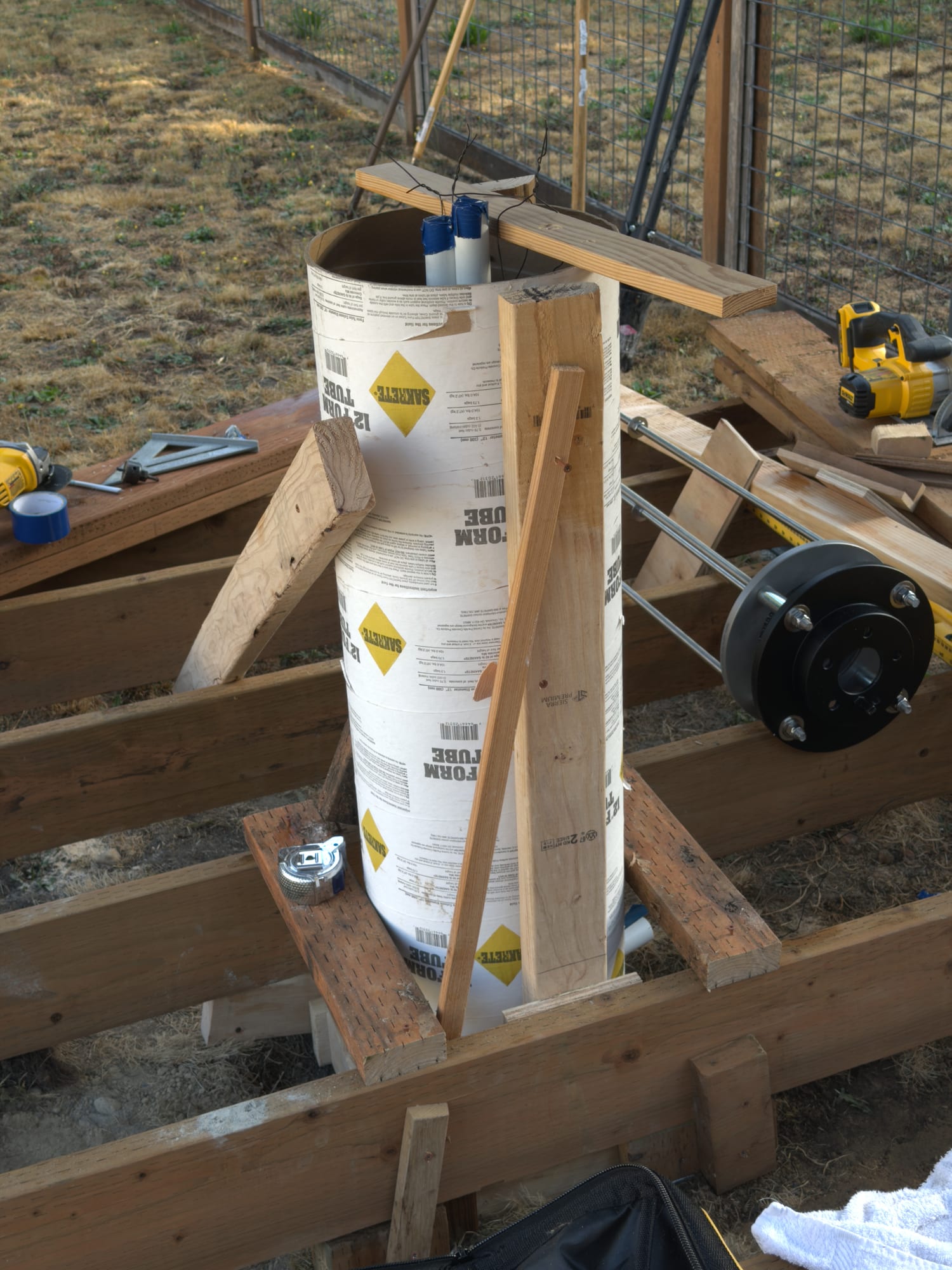
Err short. A pier an inch low takes a steel spacer under the mount. A pier an inch tall means cutting concrete.
The isolation rule
Nothing rigid may ever bridge the deck and the pier. The 1¼″ gap around the pier gets closed with a flexible boot, brush seal, or a loose trim ring resting on the decking — fastened to the deck side only, never both, and never caulked solid.
NexDome's own detail says the same thing. It is the entire reason the pier has its own footing.