Everything up to setting the adapter is recoverable. If the pour goes badly you can scrape it out and start over. The half hour after the adapter goes in is the only genuinely one-way part of the build — so the sequence is designed to push everything else off the clock.
Two sequences were considered
Pour around a suspended adapter. Hang the assembly from a crossbar, pour around the rods, done. The problem: concrete has to travel down through a ½″ annular gap and then flow back underneath an 11″ disc. With aggregate in the mix, it will not fill reliably — and a void directly under the bearing surface defeats the point of using the rotor to spread load.
Pour, then insert. Screed to ½″ below the form rim, then press the adapter down into the wet surface until paste squeezes out around the rim. You know it is solid underneath because you put it there.
The second one won, and the ½″ figure is not arbitrary: an 11″ rotor bedding about ½″ into a 12″ tube displaces roughly ½″ of concrete, so the level arrives at the rim exactly as the rotor seats.
Holding the cage
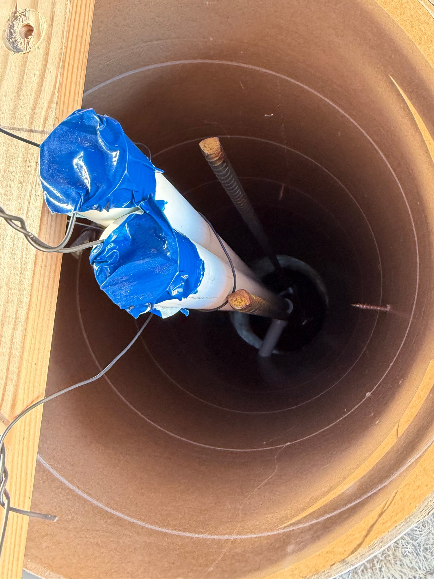
With pour-then-insert, the rods are not in place during the pour, so there is nothing to tie the cage to. The cage hangs from a stick laid across the form rim on three or four doubled tie wires — the rim is free until the adapter goes in.
Once the cage is surrounded by wet concrete, the concrete holds it. Snip the wires, lift the stick off, and set the adapter into a clear rim.
Height off the bottom is set by 3″ dobie blocks, or by placing a 4″ base lift of concrete and setting the cage into it while still plastic. Never wood, brick or fieldstone — wood rots and leaves a void, brick is weaker than the concrete around it.
The template bar
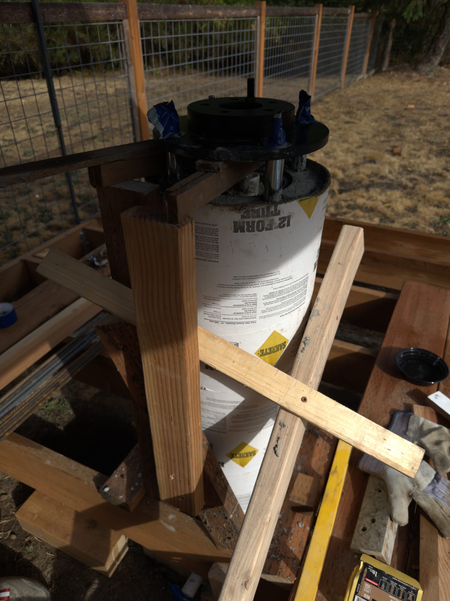
A temporary wooden bridge — two 2×4 uprights screwed to the deck joists, one crossbar between them — that holds the adapter at the right height and orientation.
The trick is that the crossbar passes through the gap between the two rotors. A 2×4 laid flat is 1½″; the spacer gap is larger. So the top rotor rests on the bar and the whole assembly hangs there, hands-free.
It sets three things at once: height, level, and rotation — because the bar can only sit one way through that gap.
Brace it properly. Two uprights and a crossbar form a rectangle, and rectangles fold. One diagonal from near the top of one upright to the base of the other makes it a triangle. Add a kicker perpendicular to that, or the frame is stiff one way and floppy the other. Two screws at each joint, never one — a single screw is a hinge.
Grab the crossbar and push hard in all four directions, then twist. It should feel dead. Whatever the frame does during the pour, the pier does too.
A caution learned here: do not let the form tube carry the load. Cardboard feels solid dry, but with 200 lb of wet concrete pressing outward it softens, and screws in wet cardboard hold very little. The uprights must go into solid joist.
Pouring
- About 12 bags of 60 lb high-strength mix for a 12″ form to this height.
- Mix on the stiff side of soupy. Ratio matters more than the extra bag.
- Place in ~12″ lifts, rodding each to release air and tapping the form sides.
- Watch the cage. If it shifts, stop and reset before continuing.
- Stop ½″ below the rim.
- Screed reasonably flat, snip the hanger wires, lift the stick off.
Tape the projecting rod threads before you pour. Cured concrete in thread roots is miserable to clean out.
Setting the adapter
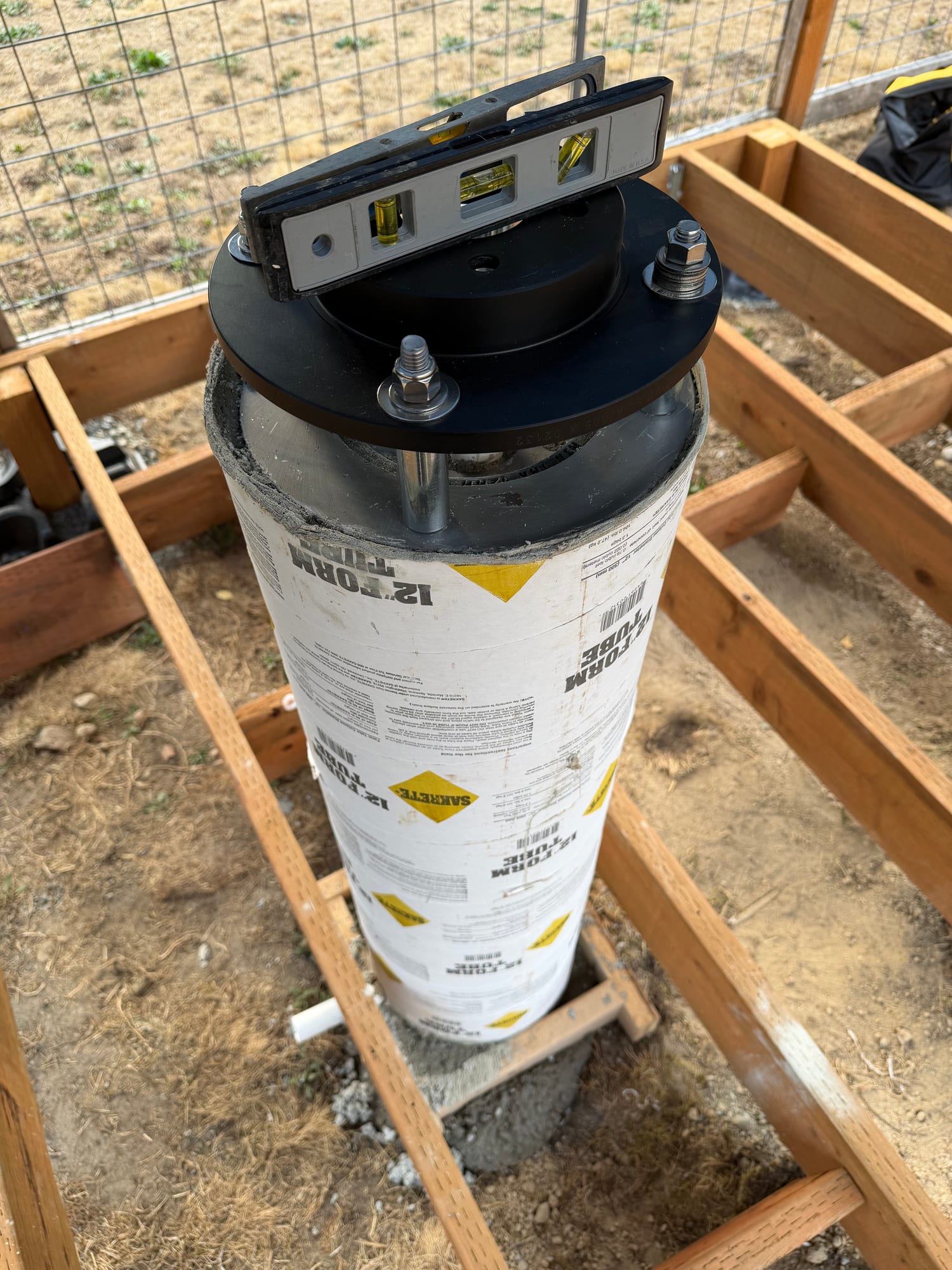
- Lower it straight down, no rocking side to side — rocking is what pushes the cage over.
- Press until the disc beds and paste squeezes out all around.
- Level on the rotor itself, at 0° / 45° / 90° / 135°. On a round plate, checking only 0 and 90 can hide a diagonal tilt.
- Sight the index rod to the north stakes.
- Plumb the rods.
- Re-check all three every 10 minutes for the first half hour. Concrete settles and things drift.
- Slope the exposed surface very slightly away from the rotor so water sheds.
Curing, and when to strip
- Do not touch it for 24 hours.
- Cover with plastic and keep it damp for at least 3 days. Concrete cured wet ends up substantially stronger — the gain is real, on the order of 30–50% over air-dried.
- At 24–48 hours: back out any screws holding the template bar and slide the crossbar out. While it is attached it links a green pier to the deck frame, and every footstep telegraphs in.
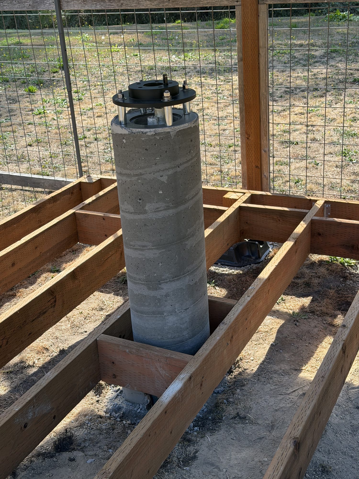
- Leave the form tube on through day 7. It is doing a second job as a curing jacket, holding moisture against the concrete.
- Strip at 7 days. It should peel in a spiral. Do not lever against the concrete edge — the arris chips easily at that age.
Loading it
50–60 lb of mount and scope is a non-issue even at day 7. At that age concrete has roughly 65–70% of its 28-day strength, and the compressive stress from a mount on a 12″ pier is well under 1 psi.
The static weight was never the concern. Torque is. Bolting the mount down means turning nuts on those rods — so go carefully, hold the nut and turn against the mount, and never grip a rod.